

Introduction
This step-by-step guide walks you through converting a surface into a solid feature in CATIA V5 using reliable methods like Close Surface and Thick Surface, along with tips for closing gaps.
Step 1: Prepare and Verify Your Surface Geometry
1. Launch CATIA V5:
Open your model in either the Wireframe and Surface Design or Generative Shape Design workbench, depending on your available licenses.
2. If working with multiple surface features, use the analysis tool to check for gaps:
- Go to: Insert → Analysis → Connect Checker Analysis
- Look for any highlighted open edges or areas.
3. Close Gaps (if needed):
- Use the Join command in the Operations toolbar to combine multiple surfaces into a single joined surface, adjusting the tolerance as needed. Gaps smaller than 0.1mm can be filled in using this tool.
- Fill openings using the Fill command in the Surfaces toolbar to patch any holes or openings between surfaces.
Step 2: Convert the Surface into a Solid
Once you have finalized your surface, you can use either of the following methods to convert it to a solid feature.
Method A (Recommended): Close Surface
Best used when your surface forms a complete enclosure.
1. Switch to the Part Design workbench: Start → Mechanical Design → Part Design
2 .Use the Close Surface command in the Surface-Based Features toolbar:
- Select your surface (works best if it forms a fully closed volume).
- Click OK.
Method B: Thick Surface
Best used if you want to add thickness to an existing surface.
1. Switch to the Part Design Workbench: Start → Mechanical Design → Part Design
2 .Use the Thick Surface command in the Surface-Based Features toolbar:
- Select the surface.
- Enter the desired thickness in either direction.
- Click OK.
Additional Best Practices
1. Import with care.
If starting from imported geometry (e.g., STEP/IGES), always analyze for gaps before attempting solid conversion.
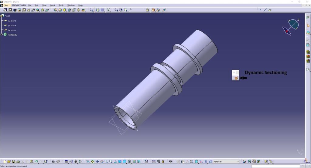
2 .Check your resulting solid by sectioning your model.
Use the Dynamic Sectioning command to verify that your solid is complete internally.
3. Use consistent naming conventions.
Label your geometric elements and solid bodies clearly to stay organized.
Common Issues & Troubleshooting
1. Issue: Gaps too large to join
Solution: Manually trim, extend, or rebuild surfaces to meet tolerance requirements, or try using the Fill command in the Operations
2 .Issue: Close Surface fails
Solution: Your surface is not fully closed or cannot be fully closed. Use the Join and Fill commands to modify your surface and try again. If you are using an open-ended surface, ensure that the open end can be enclosed by a flat face.
3. Issue: Thick Surface gives strange results or fails
Solution: Check surface curvature and continuity. Use smaller thickness values or re-work problematic regions using surfacing tools.
Quick Reference Table
| Task | Command | Workbench |
| Check for gaps in your surfaces | Insert → Analysis → Connect Checker Analysis | Generative Shape Design/Wireframe and Surface Design |
| Join surfaces | Insert → Operations → Join | Generative Shape Design/Wireframe and Surface Design |
| Fill holes or gaps | Insert → Surfaces → Fill | Generative Shape Design/Wireframe and Surface Design |
| Convert closed surface to solid | Insert → Surface-Based Features → Close Surface | Part Design |
| Add thickness to surface | Insert → Surface-Based Features → Thick Surface | Part Design |
Conclusion
By following this structured method, you can successfully convert open or closed surfaces into solids in CATIA V5. Whether you need to fill a complex volume or apply thickness to a surface, CATIA offers robust tools to support clean, reliable solid creation.